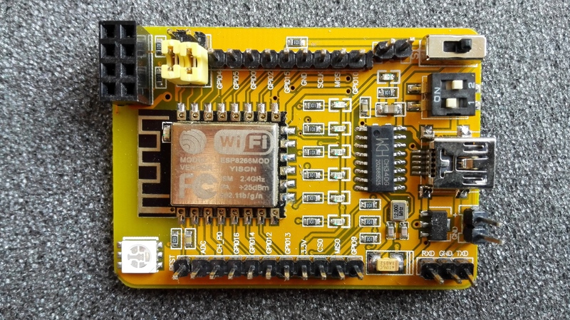
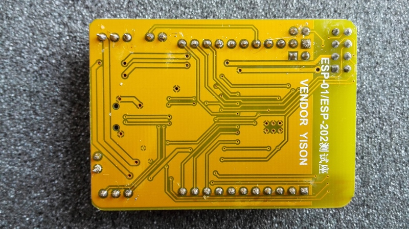
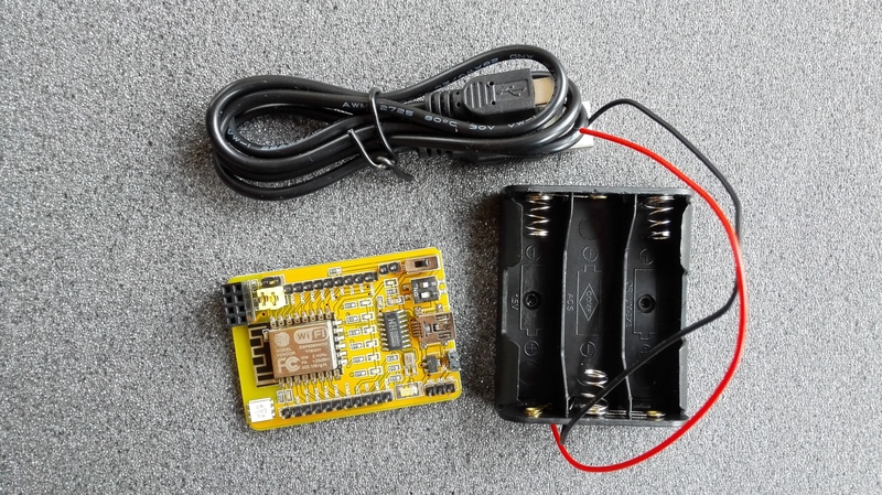
Documentation on the ESP-01/ESP-202 development board from Yison
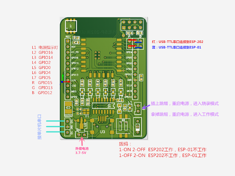
’'’On the board the labels for GPIO4 and GPIO5 are switched!’’’
| LED | GPIO | Pin |
|---|---|---|
| on module | 1 | |
| 1 | 16 | 16 |
| 2 | 14 | 14 |
| 3 | 2 | 2 |
| 4 | 0 | 0 |
| 5 | 5 | 4 |
| 6 | 4 | 5 |
| RGB/red | 12 | |
| RGB/blue | 13 | |
| RGB/green | 15 |
Pin here stands for the pin number to be used in code to access these LEDs.
int LEDS[6] = { LED_BUILTIN_1, LED_BUILTIN_2, LED_BUILTIN_3, LED_BUILTIN_4, LED_BUILTIN_5, LED_BUILTIN_6 };

void setup() {
  for(int x=0; x<6; x++) {
    pinMode(LEDS[x], OUTPUT);
  }
}

void loop() {
  for(int x=0; x<6; x++) {
    digitalWrite(LEDS[x], LOW); // switch led on
    delay(100);
    digitalWrite(LEDS[x], HIGH); // switch led off
    delay(10);
  }
}